19 Stafford Street, Brewood, Staffordshire, ST19 9DX, UK
Tel.: 01902 851009; Mob.: 07718 082150; Email: greg@greglewin.co.uk
Every organist would like to practise at home and I'm no exception. For years I have done the usual thing - practising with my hands on the piano and then driving to church to put it all together with the feet. The traditional way has worked - but I've always had the sneaking feeling that I could play much better if I could practise more in the comfort of my own home. So, rather late in life, I decided to acquire a home organ.
Where to begin? The simple answer would be to buy something ready made, but I live in a small house with no spare space for a large console. I was currently practising on a Roland stage piano - a large electronic keyboard that could maybe sit on a table - a table with space underneath for a pedalboard! By adding a pedalboard, I could develop my hand to foot co-ordination without greatly increasing the space required.
Having made this decision, I started looking about to see what was available. Ready made MIDI pedalboards can be purchased but my eye was caught by the large number of references on the Internet to folk who had modified pedalboards from scrapped pipe organs. Several had documented their projects and provided sufficient detail to give me confidence that I could do it too.
So, the decision was made. I would find an old pedalboard, fit it with switches of some sort and work out a way to feed the result into the MIDI IN of the Roland.
After spending some time on Ebay, I purchased a rather nice looking pedalboard complete with bench. The seller was also offering a pair of keyboards - so I bought those too with a view to storing them away until I had rather more space to play with. All these items appear to have been removed from the console of a theatre organ made by Compton.

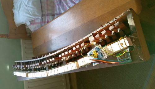
Having got my purchases home, I considered how to add the necessary switching. Many people report success with reed switches and magnets - so I decided to try that method. The reed switches were mounted in groups of 8 on blocks of wood beneath the ends of the keys. They are activated by magnets attached to the keys. The Compton pedals had adjustable rubber knobs fitted to the ends - presumably to press down on the action that opens the pedal pipes. By replacing the rubber knobs with small magnets I ended up with a mechanism that could be regulated to give the required 'touch'.

The next thing to be done was to convert the on/off action of the reed switches to MIDI. This was done based on information found here. Signals from the reed switches are sent to an Arduino Uno (an inexpensive programmable microprocessor) which packages them into the MIDI messages that are understood by the Roland piano.
Finally, I built a simple wooden table to hold the Roland stage piano at the correct height. The pedalboard could then be connected to the Roland via a MIDI cable. All worked well. A final adjustment to the code for the Arduino 'doubled' the notes at the sub-octave, giving a pseudo 16 foot effect.
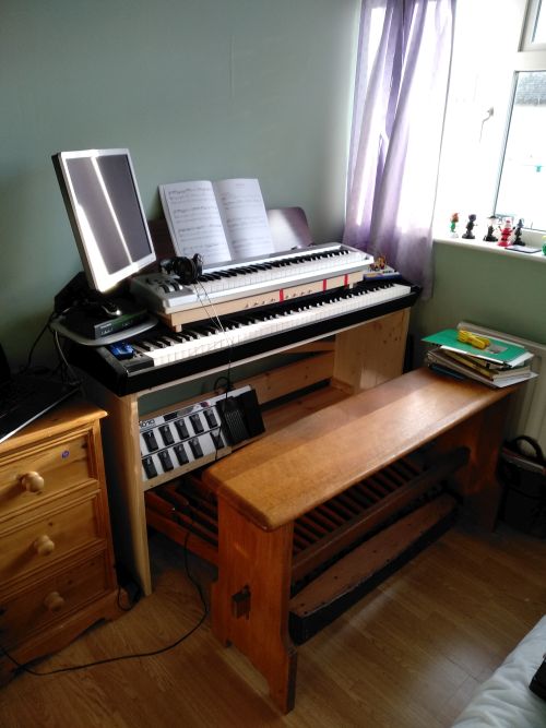
Unfortunately I forgot to photograph the 'organ' at this stage. However, by this time I had heard about Hauptwerk, a very realistic organ sampler and within a few days I had altered the setup. Both the Roland and the Compton pedalboard now acted as MIDI sources playing into a PC laptop running Hauptwerk software. This opened up the possibility of developing a much more realistic organ. I added the second MIDI keyboard seen in the photo to act as a swell manual and acquired the Behringer FCB1010 guitarist's foot controller to provide expression pedals and toe pistons. The board with three red stripes was a temporary expedient holding eight small buttons to act as thumb pistons.
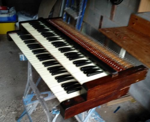
Buoyed up by the success of the project so far I turned my attention to the two rather nice Compton keyboards stored in the workshop. Would I be able to MIDIfy these too? Research on the Internet suggested that reed switches were less successful on the smaller scale of a keyboard. Some had succeeded with Hall-effect sensors and I was beginning to experiment with these when I found a paper describing the use of slotted opto-switches to MIDIfy an identical Compton keyboard. This excellent paper is so comprehensive in its coverage of the process that I just followed the instructions. I only deviated by modifying the socket arrangement to suit my Arduino based controller rather than the commercial one used by the writer of the paper (who is not named. If you know who wrote this, please let me know as I would like to credit them here).
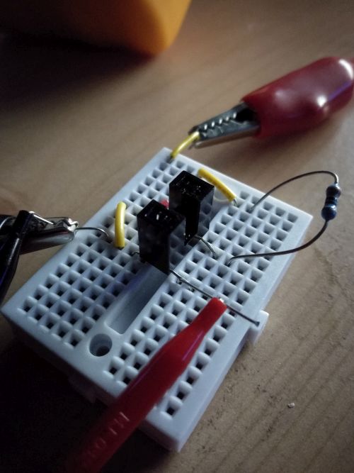
The photo above shows an opto-switch (photo-interrupter) being tested. One of the two black towers houses a light-emitting diode, the other has a photo-sensitive transistor. When an opaque shutter is placed between the two the light beam is broken. In the organ, the shutter is attached to the end of the key. When the key is pressed, the shutter is lifted out of the opto-switch, turning it on.
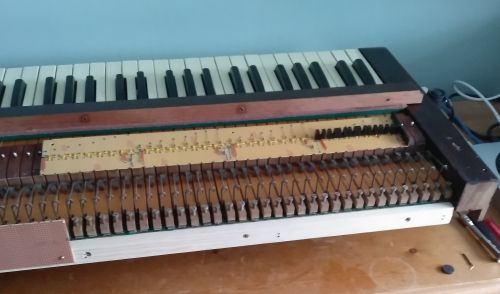
Here you can see one of the photo-interrupter boards under construction. It is made of copper stripboard (Veriboard). Many holes have been drilled to break the copper tracks where necessary, and many small jumper wires have been soldered into place. The first few opto-switches have been attached at the right hand side. The board is being made in two parts; the second part can be seen already fixed in place (bottom left in the photo).
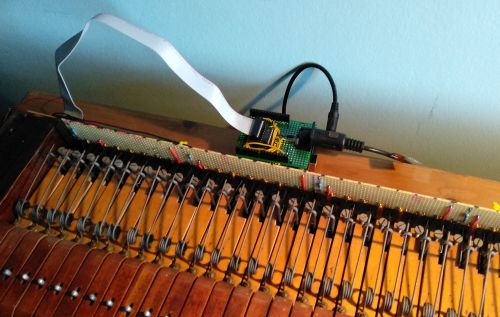
This is a view of part of the finished board in place. The Arduino Uno controller can be seen behind it, connected to the keyboard by the ribbon cable, and to the computer by the DIN lead. The shutters have been attached but are hidden in the cut-out slot at the end of each key.
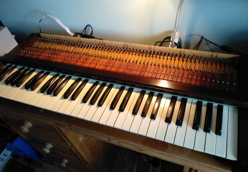
Another view of the finished keyboard.

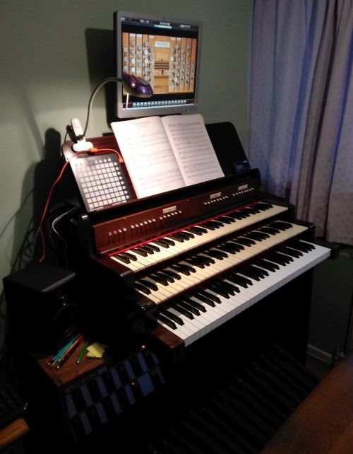
The finished two-manual organ - now looking much smarter! The music desk was a gift from the seller of the keys and pedals and probably came from the same organ. The buttons under the music desk are displaced thumb pistons. The box with coloured squares is a Novation Launchpad Mini - a MIDI controller which is standing in for draw / tab stops. Although the setup is not ideal, it provides a very usable (and inexpensive) alternative to real drawstops or touch screens.
Did you forget the second MIDI controller keyboard from the first organ? Of course I was not able to resist for very long and soon removed it from its plastic housing and made it a tray to match the Compton keyboards. It is of noticably poorer quality but it will do as a choir manual until I can source another Compton keyboard!
I was very pleased with the usability of the finished organ. It is by no means perfect but it makes a very satisfactory practice instrument. There are a number of things which I intend to improve, mainly the stop selection. I will build a proper unit for the pedalboard to replace the Behringer footboard and would like to move the thumb pistons to their rightful place beneath their manuals.
What would I do differently next time? I think it would be worthwhile designing a proper pcb for the photo-interrupter boards - the stripboard method works well but is very time consuming and fiddly. However, I was very pleased with the efficiency of the photo-interrupter system and would probably use this for the pedalboard as well. The reed switches that I used proved a little temperamental at first - I suspect that the batch I purchased contained a number of faulty units. During the first few weeks in use I had to replace a number of reed switches. Things appear to have settled down now and I have had no problems for the last few months.
Top
Back to main index
Back to organ projects index