9 Westgate, Bridgnorth, WV16 5BL, UK
Tel.: 07718 082150; Email: greg@greglewin.co.uk
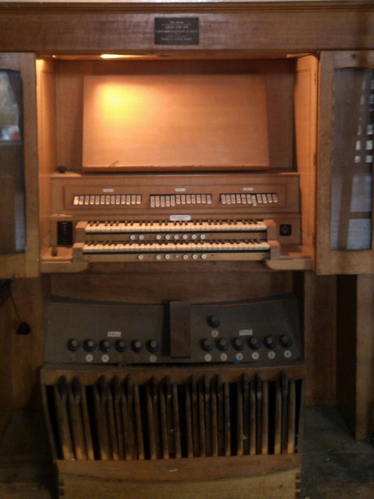
This instrument was built by Nicholson & Co Ltd for Oldbury Grammar School, Worcestershire in 1954. It was removed prior to the demolition of the school in 2015 and was offered for sale after several years in storage - latterly in less than ideal conditions. The pipework went to an organ builder and I acquired the console parts.
Details of the instrument can be seen on the National Pipe Organ Register.
I plan to use the components and the rather nice oak panelling to improve my Hauptwerk set-up. As the keyboards are almost identical to those on my current console, I may combine the two pairs to make a monster 4-manual instrument.
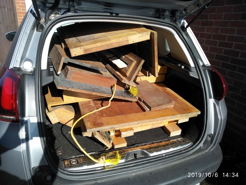
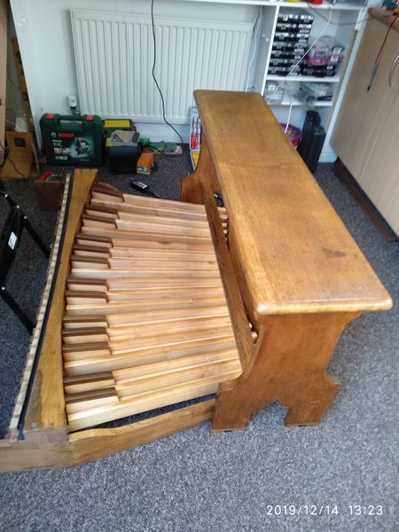
The console arrived home in two car-loads. Everything was very dusty, damp and a bit mouldy so the oak panelling was put into the shed which houses the central-heating boiler to dry out. The more delicate components were brought into the indoor workshop to dry and be cleaned.
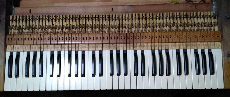
The keyboards were very dirty.
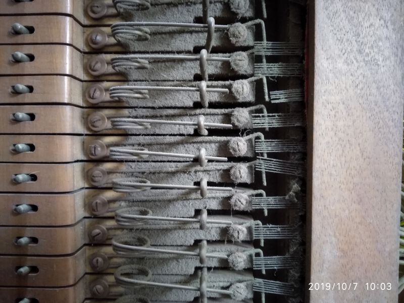
The original wire contacts were dirty and badly spark-damaged - so they were removed to make way for an optical switching system more suitable for 5 volt operation. The keys were dusted and the coverings cleaned with a damp cloth. Minor repairs (re-glueing of detached coverings etc) were made. The key-springs were modified - removing the contact end and creating space for the key shutters of the new system.
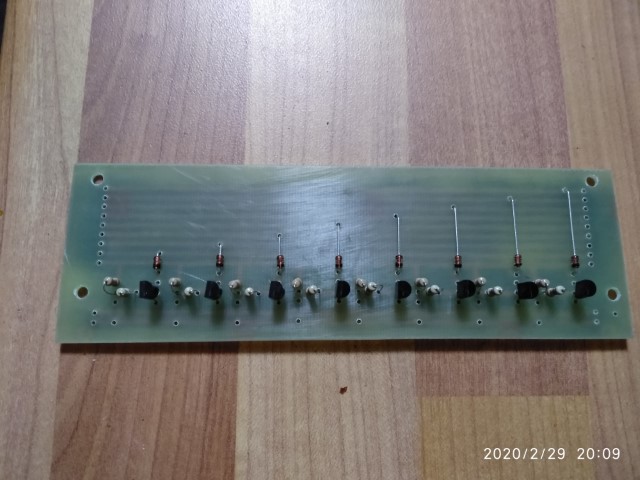
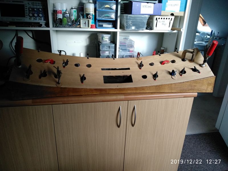
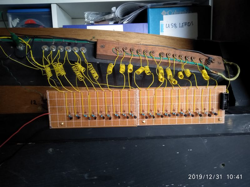
Circuit boards were made up for the new optical switching system (two boards for each keyboard).

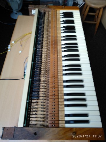
The circuit boards were mounted on new wooden rails which were attached to the back of the keyboards. Small black plastic shutters made from 7mm plastic angle were attached to the ends of the keys. The shutters were adjusted (by removing tiny amounts from the underside) to regulate the depth of touch at which each note speaks. The visible parts of the key cheeks were sanded and repolished. At this stage the keyboards have MIDI output and can be played through a sampler software such as Hauptwerk.
A buffer circuit was designed to enable the 15v signal from the thumb pistons to interface with the 5v level required by the microprocessor. Circuit boards were designed and made up and connected to the rear of the keyboards. The thumb pistons are now operational, generating MIDI messages to select stops.
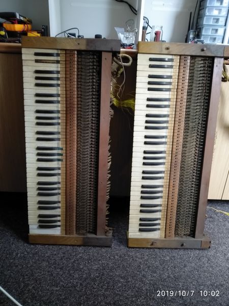
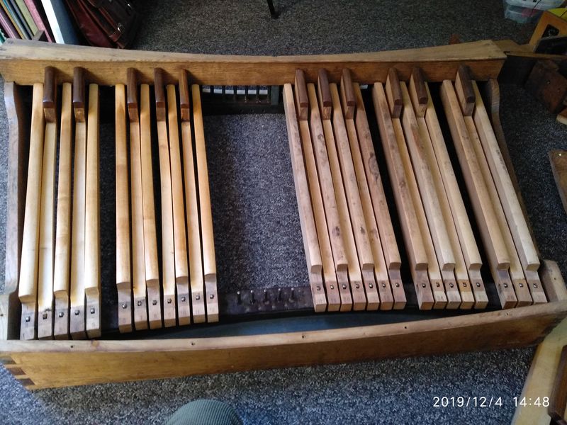
The pedalboard had broken where the tension of the toe-springs had found a weakness in one of the joints of the frame. The worn out wire contacts were removed and the whole pedalboard dismantled before being cleaned and repaired. The individual pedals were cleaned and then lightly sanded - removing what appeared to be many years of spilt school dinners. In the photograph below, the pedals on the left have just been sanded, those on the right are still to do. The picture doesn't do full justice to the improvement!
Apart from one spot of water-damage, the pedalboard cleaned up very nicely. A final coat of french polish completed the renovation.
The original 15 volt wire-contact switching system was replaced with reed switches and magnets - which seem to work quite reliably at 5 volts. Reed switches are much simpler to fit than the optical system which I will use for the keyboards. I have used both before and both seem equally reliable. The switching will be controlled by an updated version of the Arduino-based system which I have used before.
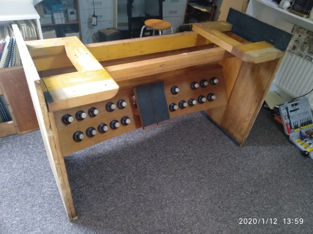
The pedal sweep had earlier been temporarily reassembled along with the pedalboard and the lower console parts while I considered how to proceed.
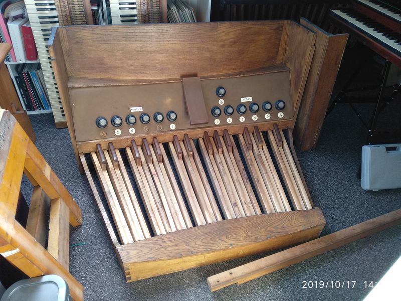
At this stage, I concluded that my original idea of building a four-manual console was impractical and I decided to go for three keyboards. To accomodate this I have rebuilt the sweep to accomodate a choir pedal and a choir to pedal stud. As I already had some matching toe studs, I took the opportunity to increase the swell and pedal divisions to eight studs each.
The original brown linoleum covering of the sweep and swell pedal had dried out, warped and broken and so was discarded. It was replaced with a second layer of 3-ply clamped and glued to the first layer - making a very strong base for the toe studs.
The new top layer was stained with a medium oak stain and then varnished. The studs and pedals were attached and wired in. The studs were provided with a 15v supply to help ensure reliable action. An electronic buffer section was added to reduce this to the 5v required by the microprocessor system.
The finished pedal section is now fully MIDIfied - so it has its voice again and can operate Hauptwerk. It begins to look quite smart!
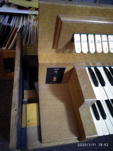
The original swell pedal had been designed to operate a physical swell box.
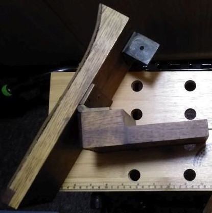
It was converted so that it now operates a variable resistor - to supply the microprocessor with the necessary control signal. The code for the Arduino needed to be adapted to change the variable voltage from the pedal to a series of MIDI control signals.
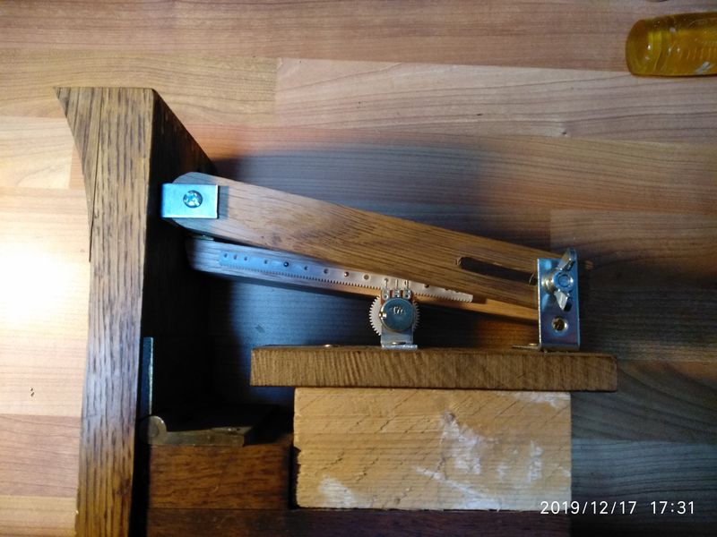
The photo shows the converted pedal mounted on a block of scrap wood. This design works well at present but I suspect that I may need to replace it with something more robust in the future.
An identical copy of this pedal was made to function as a choir pedal.
The tab unit had suffered from the damp conditions in which the console had recently been stored.
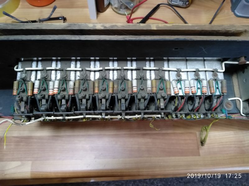
There was some damage to the wiring of the unit. Several of the stop action motor (SAM) units had failed in the past and the repairs made then were now themselves failing. The whole unit was very dirty.
I decided to dismantle the whole unit so that I could give it a thorough clean and repair.
As the tab solenoids require a voltage of about 15v at about 0.5A to operate, the original wiring loom was scrapped and replaced with a circuit board to interface the relatively high power 15v circuit with the 5v microprocessor system.
A circuit was designed and tested with a single SAM.
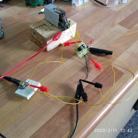
A circuit board was then designed to hold a block of eight SAMs and an arduino sketch was prepared to cycle through them - proving that they could be remotely operated under arduino control and could generate MIDI messages.
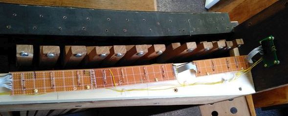
MIDI note on / note off messages can be seen being received on the laptop (Hauptwerk will understand that these are really stoptab ons and offs). The blue arduino UNO is operating the SAMs and the SAM switches are being read by the arduino MEGA with the green shield. The circuit board has been made in two sections (visible later in the video): the rear-most board holds a pair of 74HC595 shift registers and is used to trigger the solenoids in the SAMs; the nearer board handles the 5/15v switching and feeds the switch output out to the arduino MEGA. Flywheel diodes have been added across the solenoids (visible as red wires on the tops of the SAMs.)
The pcb design was slightly modified to hold both these sections on one board. It was sent to China for fabrication - unfortunately at the height of the coronavirus epidemic there. At the time of writing the boards have been made and dispatched but are yet to be received - presumably the parcel is in quarantine somewhere.
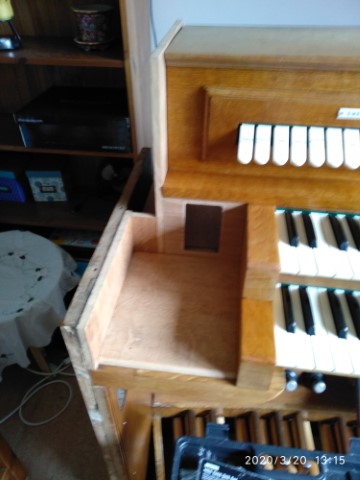
Two of the oak panels recovered from the organ casework were chosen to function as the main sides of the table.
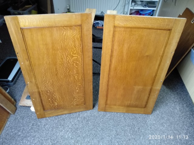
These were fixed to the sides of the pedal sweep. Two strong horizontal members were fixed between the side panels to carry the frames on which the keyboards sit.
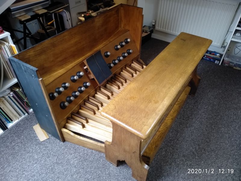
At this stage it was possible to temporarily re-assemble many parts of the original console to get some idea of the possibilities. Having seen the result I decided that it would be a shame to spoil the look of the console by adding in a third manual.
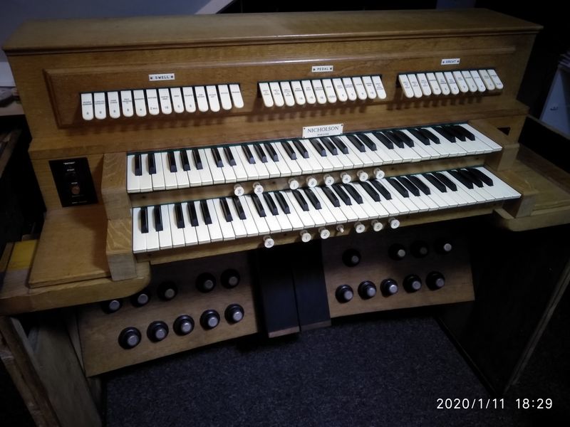
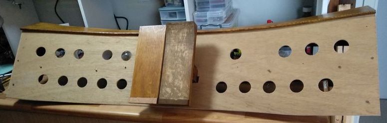
The unfinished sides of the console which were originally set into the main organ casing . . .
. . . were built up and finished.
And the original music stand was altered, refinished and fitted.
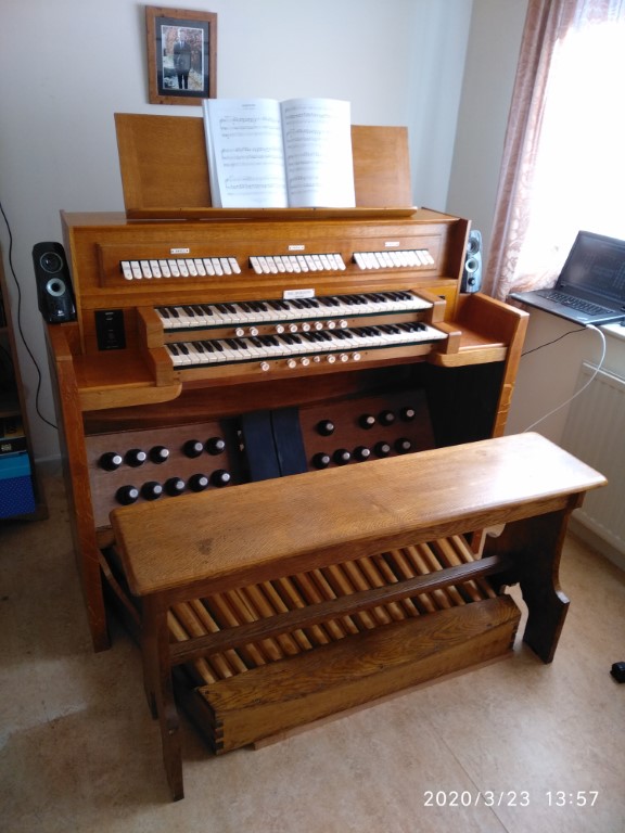
The cabinet work is now finished. Everything is working except for the tab stops which will be finished when the delayed printed circuit boards arrive from China. When the console is disassembled to enable this work to be done, I shall take the opportunity to make minor adjustments to correct a few small annoyances which have developed as the console is 'played-in'.
Top
Back to main index
Back to organ projects index