
19 Stafford Street, Brewood, Staffordshire, ST19 9DX, UK
Tel.: 01902 851009; Mob.: 07718 082150; Email: greg@greglewin.co.uk
A two manual stack consisting of a matching pair of reclaimed keyboards with twelve 'thumb buttons' set above. All mounted in a case made of oak and oak veneered board. The keys are wood-cored and appear to be covered in ivory or bone with ebony-type wood for the black notes.
The keys are switched using solid state photo-interrupters. Key presses are detected by a microprocessor which generates appropriate MIDI messages to be sent to a computer hosting Hauptwerk or similar software. The microprocessor system has three inputs, two being used by the keyboards and thumb buttons; the third is unused and could service a separate pedalboard, expression pedals and toe pistons etc.
The two manual stack was built to provide a replacement instrument for use during rebuilding work on the organ at the church where I play. When that task is done, the stack will probably be offered for sale.

The project began with the purchase of a two manual keyboard stack from a seller living in Lichfield, Staffordshire. Nothing is known of the organ from which it came - although it appears to have had some type of mechanical action. The keyboards had already been subject to MIDIfication as a result of which the keys had been shortened -resulting in a rather unreliable action on the upper manual. The first conversion had used reed switches - which I was told had been unsuccessful; these had been removed before I purchased the keyboards.

The white keys are covered in a natural material - probably ivory or bone. The black keys are black ebony-type wood.

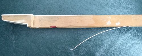
I first noticed the keyboards for sale on Ebay when I was researching ways of springing the Horton Chapel stack. My first idea for the springing had been to alter the key end adding a captive torsion spring as on this keyboard which I used in an earlier project. However I was unable to source suitable phosphor bronze wire and piano wire proved too springy!

The Lichfield keys appeared to be sprung from beneath so I purchased them to find out how. The answer was very simple. They use piano wire, shaped to provide a hole for a screw at one end and a simple bend at the other to prevent the wire from digging in. The system is similar to the way that most pedalboards are sprung.
The keys had been shortened during the previous attempt at MIDIfication, making it difficult to assess the action of the original instrument. However the serial number 2151 remains, stamped on the lowest two keys of the upper manual - possibly a clue to the identity of the donor organ!

For my first attempt at adding switches to a keyboard I had followed instructions found on the internet. This involved mounting the photo-interrupters on stripboard and required lots of soldered links and precision placed holes. This time I thought I would try something different (and hopefully easier) so I used the open-source Fritzing electronics design program to create a pcb layout and created custom printed circuit boards to hold the photo-interrupters.

The layout was laser printed onto shiny paper and heat transfered onto single sided copper-faced board.

The board was then etched with ferric chloride and carefully cleaned off. All that now remained to be done was to drill out the holes. The eagle-eyed will notice that the above photograph shows an early prototype board which I managed to etch as a mirror image of the required design! Four of these boards are used for each 61 note keyboard. The vertical rows of holes allow the end board to be shortened to accommodate 56 and 58 note keyboards. Although this process was much simpler than using stripboard, it was still very time-consuming. Next time I will have the boards manufactured for me.

The boards were then made up -

- stitched together in sets of four and fitted to a wooden rail fixed at the end of the keys. The photo above shows one set of boards fitted in place for the upper manual. Two more boards have been stitched together and sit on the keys along with their as yet unconnected socket board. Notice that the right most of the two stitched boards has been shortened to accommodate the 58 key range of the manuals.

The square black 'n' shaped components attached to the pcb are the photo-interrupters. Each has a light emitting diode in one arm and a detector in the other. Shutters made from 7mm black plastic angle section are glued to the key ends to interrupt the light passing between the two arms of the photo-interrupter, keeping it switched off while the key is at rest. When the key is pressed the shutter lifts up and allows light to pass turning the circuit on.

Key activity is detected by an Arduino Uno (a self-contained microprocessor unit which can be programmed using a variant of the C programming language). These devices are inexpensive and well documented and supported. The photo shows a 'shield' which plugs into the top of the arduino allowing it to be connected via a ribbon cable to the keyboard and via the socket marked 'OUT' to the MIDI IN connector of a computer system hosting Hauptwerk or similar. For the finished project I redesigned the shield to use the slightly larger Arduino MEGA 2560: this provides input sockets for two keyboards and a pedalboard.

Another view of the photo-interrupter board fitted to the rear of the swell keys.

This last photo shows the twelve thumb buttons about to be wired in. These appear to MIDI as a further six notes at the top of each of the two manuals but Hauptwerk can assign them to almost any of its functions. I have set them up as five thumb pistons for each manual along with a swell to great coupler and a general cancel. The felt covered bar across the swell keyboard was added to prevent the shortened keys being lifted off the balance pins by the springing.
The final result looks good and works well. Stop control is currently achieved using a 64 button Novation Launchpad Mini. A pedalboard has been aquired and will be MIDIfied when time allows. I may also experiment with using LED illuminated buttons mounted on jambs in drawstop fashion.
The springing system inherited from the previous conversion works satisfactorily but might be improved if the springs were attached the other way around. In their present position the springs tend to push the shortened keys of the upper manual off their balance pins - causing keys to stick occasionally - the rather unreliable action mentioned above. The problem has been solved here by placing a shaped and felted bar across the upper manual between the rows of balance pins.
Another difficulty caused by the springing system is that the keys are only held in their correct positions when the whole unit is assembled. It is not possible to work on the lower manual without rigging up some kind of temporary measure to hold the keys in place. This makes regulating the action more difficult.
Top
Back to main index
Back to organ projects index